Views: 0 Author: Site Editor Publish Time: 2026-08-21 Origin: Site
Commercial environments are shifting from static architecture to dynamic spaces. This shift drives the demand for non-traditional digital canvases. Conceptualizing a custom digital display is straightforward on paper. Executing it requires reconciling ambitious aesthetic visions—like continuous curves, suspended spheres, immersive tunnels, and forced-perspective 3D corners—with strict engineering realities. You have to manage structural load capacities, thermal management limits, and long-term serviceability requirements.
Moving from a design concept to a functional installation requires a rigorous evaluation framework. Treating these installations as simple audiovisual peripherals leads to structural conflicts and operational failures. This guide breaks down how to specify, evaluate, and implement a Creative Design LED Screen without compromising structural integrity or visual storytelling capabilities. We align architectural intent with hardware capabilities so you can deliver seamless digital environments that operate reliably over their intended lifespan.
Form Dictates Engineering: The physical shape of a creative design LED screen (flexible, transparent, or geometric) directly impacts structural requirements, power consumption, and cooling needs.
Maintenance Access is Critical: Custom shapes often complicate serviceability; specifying front vs. rear maintenance during the design phase prevents costly structural modifications post-installation.
Content Mapping Complexity: Non-standard aspect ratios, 360-degree sculptural displays, and 3D configurations require specialized media servers and control systems capable of pixel-accurate mapping.
Table of Contents
Establishing the primary objective of the installation dictates every subsequent hardware decision. Project teams must determine whether the display serves as an ambient architectural enhancement or a high-fidelity medium for information delivery. Ambient displays often utilize lower pixel densities and prioritize seamless physical integration. They act as digital textures rather than focal points. High-fidelity storytelling requires precise color reproduction, high contrast ratios, and specialized content management systems.
Evaluating ambient light conditions dictates the required diode specifications. Indoor environments with extensive natural light from glass atriums require displays capable of reaching 1,500 to 2,500 nits to prevent image washout. Fully outdoor installations demand 5,000 to 10,000 nits alongside robust weatherproofing. Failing to match the hardware’s brightness capabilities with the site’s specific photometric realities results in displays that are unreadable during peak daylight or blindingly overpowering in low-light conditions. You must conduct a site survey with a light meter at various times of day to establish the baseline nit requirement.
Pixel pitch determines the optimal viewing distance and directly influences the physical properties of the display. Calculating the necessary pixel pitch requires analyzing the closest point at which an audience will interact with the screen. A standard industry metric suggests one millimeter of pitch for every meter of viewing distance. A screen viewed from three meters away requires a pixel pitch of 3mm or finer to appear seamless.
There is an inverse relationship between pixel pitch density and the physical flexibility of the LED modules. Highly flexible modules designed to wrap around tight architectural columns often utilize larger pixel pitches. Densely packed diodes limit the printed circuit board's (PCB) ability to bend without fracturing solder joints. Specifying a display requires balancing the need for visual clarity with the structural demands of the intended curvature.
Pixel Pitch (mm) | Optimal Viewing Distance | Typical Application | PCB Flexibility Impact |
|---|---|---|---|
1.2mm - 1.9mm | 1 to 2 meters | Interactive lobbies, broadcast sets | Highly rigid; requires flat or faceted mounting |
2.5mm - 3.9mm | 3 to 4 meters | Retail interiors, curved architectural walls | Moderate flexibility; supports gentle curves |
4.8mm - 6.0mm | 5+ meters | Outdoor facades, large suspended spheres | High flexibility; supports tight column wrapping |
Modern digital installations frequently move beyond passive playback to incorporate interactive capabilities. Defining the need for interactivity—such as capacitive touch overlays, optical motion tracking, or LiDAR-triggered content—must occur during the schematic design phase. These features require dedicated hardware layers and specialized glass or polycarbonate protective coatings that add weight and depth to the installation.
Real-time, reactive content rendering demands specific hardware and latency requirements. Interactive systems must achieve sub-20 millisecond latency to feel responsive to human input. This necessitates high-refresh-rate LED receiving cards, localized rendering servers, and robust fiber-optic data infrastructure to prevent bottlenecking. Delayed or stuttering responses immediately break the immersive experience and render the interactive elements useless.
Integrating digital canvases into physical architecture requires defining acceptable physical gaps between custom modules and existing architectural elements. Custom installations often interface directly with millwork, structural columns, or glass facades. Establishing strict integration tolerances—often measured in single millimeters—ensures a flush, built-in aesthetic.
Achieving these tight tolerances requires precise site surveys using 3D laser scanning before fabricating the mounting frames. Any deviation in the physical wall or column must be accounted for in the adjustable Z-axis brackets of the display structure. You cannot rely on standard architectural drawings, as as-built conditions always vary. Failure to manage these tolerances results in visible dark lines, uneven panel seams, or protruding edges that ruin the illusion of a continuous digital surface.
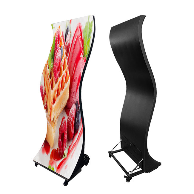
Flexible LED modules utilize specialized soft PCBs and pliable silicone masks, allowing them to conform to non-linear surfaces. These modules are the primary solution for wrapping structural columns, creating wave-like ceiling installations, continuous curved walls, and immersive walk-through tunnels. Their ability to bend eliminates the faceted, blocky appearance that occurs when attempting to create curves with rigid, traditional cabinets.
When evaluating flexible modules, the minimum bending radius is the most critical specification. Pushing a module past its rated bending radius causes immediate diode failure and PCB delamination. Evaluate the mounting mechanism carefully. Magnetic chassis systems allow for rapid front-serviceability and seamless alignment on curved metal sub-frames. Screw-mounted systems offer higher security for ceiling or high-vibration environments but complicate maintenance procedures.
Transparent LED technology provides light transmission without obstructing architectural sightlines. These displays are heavily utilized in retail storefronts, glass atriums, and stage backdrops. By embedding micro-LEDs into transparent polycarbonate films or weaving them into lightweight aluminum meshes, these screens allow natural light to enter a building while displaying high-contrast video content to the exterior.
The primary evaluation criterion is the ratio of transparency percentage to pixel density. Higher transparency requires wider gaps between pixel rows, which reduces the overall resolution. Project teams must balance the need for clear sightlines with the required image fidelity. For window-facing applications, UV resistance is paramount. The transparent film or mesh must feature industrial-grade UV inhibitors to prevent yellowing and diode degradation caused by prolonged sun exposure.
Geometric displays break away from flat planes entirely, forming three-dimensional sculptural presences. This category includes LED cubes, display towers, suspended spheres, forced-perspective 3D corners, and irregular polygonal grids. These installations act as central architectural features, drawing attention from multiple vantage points and requiring content to be mapped across multiple distinct faces simultaneously.
Executing geometric displays requires custom PCB design to fit non-rectangular shapes, such as triangles or trapezoids. Corner-gap minimization techniques are critical. The physical seams where two planes meet must be engineered to less than a millimeter to maintain the illusion of a solid digital object. The structural framing complexity for multi-sided viewing is significantly higher than flat walls, requiring internal skeletal structures that support the weight of the modules while housing internal power and data distribution.
To successfully deploy a geometric display, follow this specific installation sequence:
Install the primary internal steel or aluminum armature, anchoring it to the building's structural load points.
Mount the secondary micro-adjustment brackets, using laser levels to ensure perfect alignment across all intersecting planes.
Route all power and data cabling through the internal armature, securing lines away from heat sinks and sharp metal edges.
Attach the custom-shaped LED modules starting from the most complex intersection (e.g., the point of a 3D corner) and work outward.
Perform a full white-screen test to identify and calibrate any color shifts across the different geometric faces.
Every custom digital installation begins with a rigorous structural analysis. Engineers must assess the dead load, which includes the total weight of the LED modules, mounting frames, cabling, and internal power supplies. For outdoor or semi-exposed setups, live loads such as wind shear, seismic activity, and thermal expansion must be factored into the structural calculations. Overloading existing architectural infrastructure poses severe safety risks and leads to catastrophic failure.
Standard flat-wall mounts are rarely sufficient for custom shapes. Evaluating the necessity of custom-fabricated aluminum or steel sub-frames is a mandatory step. Aluminum offers a high strength-to-weight ratio and natural corrosion resistance, making it ideal for suspended or weight-restricted environments. Steel provides maximum rigidity for massive, ground-supported geometric towers. These sub-frames must be engineered with micro-adjustment capabilities to ensure the LED modules align perfectly, regardless of imperfections in the host building's structure.
Non-traditional shapes introduce complex viewing angle challenges. On 360-degree sculptural displays, audiences view the screen from extreme off-axis angles. This results in noticeable color shift and brightness degradation if the diodes are not optimized for wide-angle dispersion. Specifying hardware with a minimum 160-degree horizontal and vertical viewing angle is essential for maintaining image integrity across curved or multi-sided surfaces.
Ensuring uniform diode batching across all visible planes is critical to maintain seamless visual continuity. LED diodes are manufactured in batches, and slight variations in color temperature and brightness exist between batches. For a multi-sided cube or a continuous tunnel, mixing batches results in visible patchwork. Procurement contracts must stipulate that all modules for a specific project are sourced from a single, tightly calibrated diode bin.
High-density digital displays generate substantial heat, and custom shapes often trap this heat in enclosed spaces. Calculating maximum power draw is the first step in designing the electrical infrastructure. Installations require dedicated circuits, proper phase balancing, and industrial-grade surge protection to ensure stable operation. A massive 3D corner display can easily draw tens of kilowatts at peak white levels, requiring heavy-duty electrical retrofitting.
Designing the cooling system is equally critical. Passive cooling relies on heat sinks and natural convection, which is sufficient for low-brightness indoor screens with ample rear clearance. Enclosed geometric shapes or recessed architectural screens require active cooling systems. This involves integrating forced-air extraction fans or tying the display enclosure directly into the building's HVAC system. Failure to manage thermal output leads to thermal throttling, rapid diode degradation, and premature hardware failure.
Cooling Method | Application Scenario | Infrastructure Requirement | Maintenance Frequency |
|---|---|---|---|
Passive Convection | Open-air indoor displays, low brightness | Minimum 10cm rear clearance | Low (Annual dusting) |
Active Forced Air (Fans) | Enclosed geometric shapes, high brightness | Intake/exhaust vents, dedicated power | Medium (Quarterly filter checks) |
HVAC Integration | Recessed architectural walls, outdoor enclosures | Ducting connected to building return air | High (Requires facility management coordination) |
The hardware is only as capable as the control system driving it. Standard digital signage controllers cannot handle the demands of custom shapes. Evaluating advanced media servers capable of handling non-standard resolutions, complex geometric mapping, and multi-canvas synchronization is mandatory. These systems must ingest massive, custom-resolution video files and distribute them accurately across thousands of individual receiving cards.
For forced-perspective 3D content and interactive sensor integration, assessing latency, refresh rates, and color depth is vital. Forced-perspective illusions require ultra-high refresh rates (typically 3840Hz or higher) to prevent flickering when viewed through smartphone cameras. 10-bit or 12-bit color depth processing ensures smooth gradients in custom content, eliminating the color banding that ruins the realism of 3D visual effects. Fiber optic cable runs are often required between the media server and the display to handle the massive data bandwidth without signal degradation.
Project teams constantly face the trade-off between fully bespoke engineering and leveraging standardized flexible components. Fully bespoke PCB shapes, designed specifically for a unique architectural curve or sharp angle, offer the most seamless physical integration. They carry high upfront engineering requirements, extended manufacturing timelines, and difficult replacement logistics. If a custom-shaped module fails five years post-installation, sourcing an exact replacement is highly problematic.
Utilizing standardized flexible modules simplifies long-term maintenance. These modules are mass-produced and easily stockpiled as spares. The trade-off is that standard modules limit extreme design geometries. They have fixed minimum bending radii and cannot form sharp, non-standard angles without visible seams. Teams must weigh the desire for absolute architectural perfection against the practicalities of long-term hardware support.
The method of maintenance access dictates the physical footprint of the installation. Front-serviceable magnetic modules allow for flush wall mounting, maximizing floor space and providing a sleek, built-in aesthetic. Technicians use specialized magnetic suction tools to remove individual modules directly from the viewing face. While space-saving, this method requires careful handling to avoid damaging the exposed diodes during extraction. Re-aligning the modules on the Z-axis after servicing can also be tedious.
Rear-serviceable screens are generally easier and safer to repair. Technicians access the power supplies and receiving cards from behind without touching the delicate LED face. Rear access demands dedicated catwalks or a minimum of 60 to 80 centimeters of structural depth behind the screen. Specifying the serviceability method during the schematic design phase prevents catastrophic scenarios where a screen must be entirely dismantled to replace a single failing power supply.
Maintaining the visual integrity of a custom display over a ten-year lifespan requires a rigorous spare parts strategy. Because LED diodes degrade at specific rates based on their manufacturing batch, you cannot simply buy a replacement module off the shelf three years later. The new module will appear noticeably brighter and have a different color temperature than the surrounding aged modules.
You must procure a comprehensive spare parts package at the exact time of the initial order. This package should include 3% to 5% extra LED modules, spare receiving cards, and backup power supplies, all manufactured from the exact same diode bin as the primary screen. Storing these spares in a climate-controlled environment ensures you have color-matched replacements ready for immediate deployment when hardware inevitably fails.
Integrating large-scale digital architecture introduces strict regulatory oversight. A primary risk is failing local fire inspections due to the use of improper materials or blocking established egress routes with protruding sculptural displays. Building inspectors will halt operations if a custom structure impedes sprinkler coverage or narrows a hallway below fire code minimums. ADA compliance is also a factor if a screen protrudes more than four inches from a wall in a pedestrian pathway.
Mitigation requires specifying fire-retardant materials across the entire build. All cabling must be plenum-rated, and the LED modules and power supplies must hold rigorous UL, CE, or local equivalent certifications. Engaging structural engineers and local code officials during the earliest schematic design phases ensures that the physical footprint, weight distribution, and material composition comply with all municipal safety regulations before fabrication begins.
Custom digital installations are highly susceptible to schedule overruns. Delays are frequently caused by custom manufacturing timelines, international shipping bottlenecks, or misaligned structural framing discovered upon site arrival. If the custom aluminum sub-frame does not perfectly match the site's concrete columns, the entire installation halts while parts are re-fabricated.
To mitigate these risks, project managers must require detailed CAD and BIM models from the vendor, integrating them directly into the master architectural model. Utilizing 3D laser scanning for site preparation ensures the mounting brackets are engineered to the exact millimeter of the as-built environment. Furthermore, you must mandate Factory Acceptance Testing (FAT) prior to shipping.
A proper FAT protocol includes:
Assembling the entire custom structure on the manufacturer's floor.
Running the display at 100% white for 48 hours to test thermal stability.
Mapping the actual project content to verify media server performance.
Testing the extraction and replacement of modules using the designated maintenance tools.
Executing a non-traditional digital display requires balancing ambitious architectural design with rigorous engineering standards. To ensure your custom vision operates reliably over its intended lifespan, partnering with an experienced industry manufacturer is essential. Bringing decades of optical innovation and custom manufacturing expertise, Shenzhen Lightingart LED Display Co., Ltd. provides high-performance, tailored LED display solutions engineered to transform complex architectural concepts into breathtaking, high-reliability visual environments.
Initiate a comprehensive site survey with an AV consultant to map ambient light levels and precise physical dimensions.
Request formal structural engineering reviews for all proposed mounting locations to verify dead and live load capacities.
Demand a physical proof-of-concept (POC) from shortlisted vendors to validate complex geometric mapping and off-axis viewing angles.
Secure a dedicated workflow for custom content creation tailored specifically to the unique aspect ratio and physical shape of the final display.
A: The minimum bending radius depends heavily on the pixel pitch and the flexibility of the printed circuit board. Tighter pixel pitches have larger minimum bending radii to prevent mechanical stress from damaging the densely packed diodes and underlying circuitry. Pushing a module past its specified limit causes immediate hardware failure.
A: Power requirements are calculated by multiplying the maximum power consumption per square meter by the total square meterage of the screen. Engineers must then factor in a 20% to 30% overhead margin for safety, electrical fluctuations, and peak brightness usage during pure white content rendering.
A: Creative LED screens require advanced control systems and specialized media servers capable of mapping content across irregular shapes, non-standard aspect ratios, and multiple separate physical canvases simultaneously. Standard systems typically only handle simple rectangular grids and standard 16:9 or 4:3 video resolutions.
A: Multi-sided displays require specialized media servers. These servers slice a single, ultra-high-resolution video file and map the corresponding sections to specific geometric faces of the display. This ensures seamless playback, frame synchronization across corners, and accurate rendering from all viewing angles.
A: Yes, but outdoor creative screens require stringent engineering. They must feature high IP ratings for complete weatherproofing, significantly higher brightness outputs to compete with direct sunlight, and robust structural sub-frames designed to withstand local wind shear and seismic loads.
A: Ventilation requirements depend entirely on the screen's total thermal output and the volume of the enclosure. Recessed, flush-mounted, or enclosed geometric screens trap heat and require active HVAC integration or forced-air extraction fans to maintain optimal operating temperatures and prevent hardware failure.